Problems of elliptical wing design and practical implementation on the Ellipse ultralight aircraft
21. June 2022
It is well known that a wing planform is the optimal solution in terms of induced drag and efficient use of wing area. The proof is in the aircraft whose designers have chosen this somewhat more tedious route to enable them to achieve the highest performance. It is not for nothing that these wings are found on special speedsters and fighters.
In its day, when wooden and metal structures were common, the production of an elliptical wing was a major technological challenge. But what about today? Is technology really the only problem with using an elliptical wing, or is there more to it? The following text will address these questions.
Technology
So let's start with the technology. The surface of an elliptical wing is not a straight surface, but a collapsed surface (or a surface of double curvature). This places high demands on the production of not only the wing skin (panel pressing, complex bending in both directions, etc.) but also its other parts (e.g. the spar, whose chords are curved). It is easy to say that nothing is straight on an elliptical wing.
In addition to the aforementioned high manufacturing requirements, this results in a much more demanding check of the correctness of the wing shape.
However, nowadays CNC technology and laser measuring equipment are available and, in conjunction with composite materials, we have powerful tools that allow us to produce an elliptical wing much more easily than was previously the case. It goes without saying, however, that even today the production of such a wing will be somewhat more challenging than the production of a rectangular or trapezoidal wing.
Geometry
As already outlined, the complex geometric shape of the wing causes many sub-problems which are constantly encountered throughout the design, construction and production process. Examples include the thinning thickness of the trailing edge towards the end of the wing (for practical reasons it is preferable to keep it constant), or the fact that the theoretical axis of aileron rotation or the axis around which the flap extends can also be spatial curves.
Substituting such a curve with a straight line (otherwise the flap could not be extended) causes that the optimal flap position in this case is only maintained in (at most) two of its sections and thus its efficiency decreases.
On the other hand, an elliptical wing, due to its geometry, may pleasantly surprise us with a favourable weight distribution along the span or the fact that the aforementioned collapsed wing surface is likely to have better shape stability than a straight wing surface, which may lead to weight savings in the wing design.
Distribution of lift coefficient along the wing span
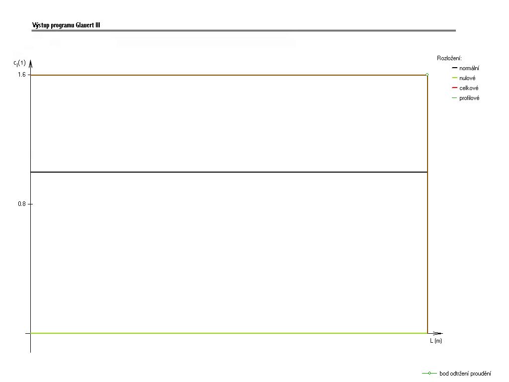
All the problems associated with the aerodynamics of an elliptical wing center around the distribution of the lift coefficient along the span. A constant distribution is ideal from the point of view of induced drag and the wing is efficiently used without any residual drag (Fig. pure ellipse).
However, from a practical point of view, it is necessary to ensure a correct and predictable behaviour of the aircraft and therefore to create a certain reserve of lift coefficient in the aileron region, which will be guaranteed in all flight configurations.
The lift coefficient margin is determined from the difference between the maximum local profile lift coefficient and the lift coefficient at that location, which is determined by the distribution of the lift coefficient along the span. The progression of this distribution can be obtained, for example, using the Glauert method.
Let's talk about the behaviour of the lift coefficient distribution along the wing span. If we are working with a linearized problem (which the Glauert method is), the lift coefficient distribution curve is the result of the superposition of the individual components. Thus, we have a distribution of the lift coefficient along the span. The other components modify the shape of this curve, but are of the nature of a null distribution.
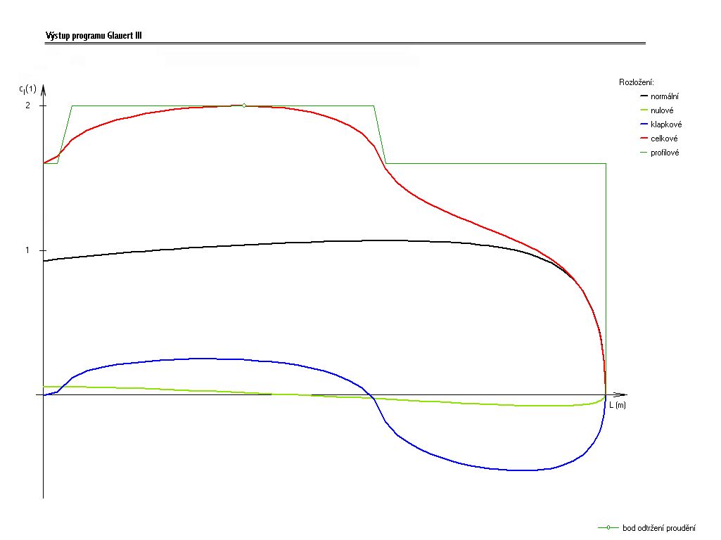
This means that their integration along the span gives a zero total lift coefficient increment. Or more simply, the area representing the increase in lift coefficient is equal to the area representing the decrease in lift coefficient. What changes the shape of the lift coefficient distribution is, for example, a linear change due to geometric twisting (Fig. Example).
The first problems do not wait long. If we consider a pure flight configuration of an untwisted elliptical wing (geometrically and aerodynamically), the distribution of lift coefficient and maximum profile lift coefficient along the span will be identical.
Thus, the lift coefficient margin on the ailerons is zero and flow separation should occur simultaneously over the entire wing span. In reality, the situation is a little worse because we have not yet considered the effect of the Reynolds number. It is known that as the Reynolds number increases, virtually all airfoil properties improve, including the lift coefficient and critical angle of attack, which are essential in this case.
Therefore, when considering the effect of Reynolds number, which decreases towards the wing tip, the airfoil properties deteriorate in the same way and it is likely that the flow separation will occur first in the aileron region, which is undesirable from the point of view of airplane controllability.
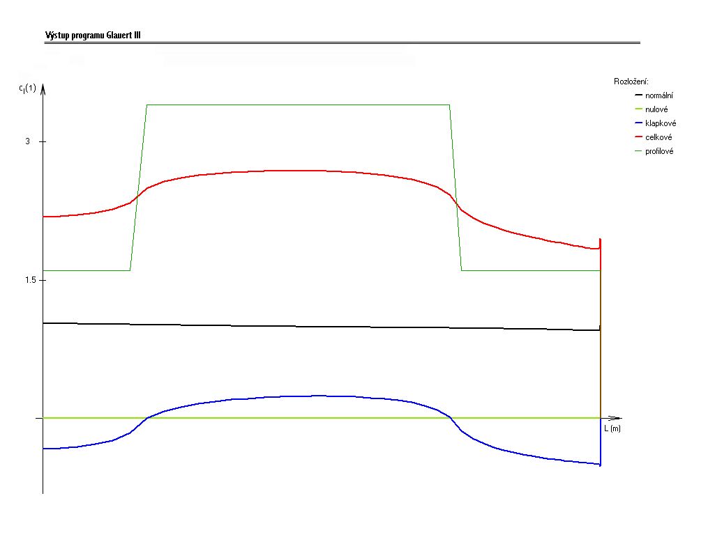
The worst situation occurs in the landing configuration. In an elliptical layout, it is precisely the effect of the constant distribution of the lift coefficient over the span that causes this distribution to decrease only very reluctantly outside the flap, causing the local maximum profile lift coefficient to be exceeded outside the flap and thus flow separation at these locations (Fig. Ejected_flap).
The hull has another negative effect here. As there is often no flap below the fuselage, the lift coefficient value for a flap layout has the potential to drop not only in the aileron area but also in the fuselage area. This unfortunately makes the aileron situation worse, because if the flap were also under the fuselage, the ailerons would experience a much more pronounced drop in the lift coefficient curve due to the flap distribution.
This brings us to the next problem. In order to reduce the lift coefficient value on the aileron from the distribution below the maximum lift coefficient of the airfoil, we cannot use a very efficient flap that has a large increment of lift coefficient over the clean airfoil. And since the wing is being designed for minimum speed, then the wing area must be increased to achieve the required lift for the minimum speed required.
This will of course have a negative effect on the maximum speed at which the frictional drag of the wetted surface of the aircraft (i.e. the wing) is a critical component of the overall drag.
In order to provide a reserve of lift coefficient in the aileron region, various means can be used. One of the simplest is to twist the wing. This can be either geometric (the trailing edge has a lower angle of attack relative to the root airfoil) or aerodynamic (a higher maximum lift coefficient airfoil or higher critical angle of attack is used at the wing tip). Often it is a combination of both. Furthermore, the wing planform can be modified so that the wing loading is lower at a given location (e.g. so-called "dog tooth").
Another option is a mechanical solution (means to increase lift, symmetrical aileron upward deflections, etc.). However, any such intervention in the elliptical wing will result in an increase in induced wing drag. Then, of course, it may also happen that a complex elliptical wing will have the same induced drag as a suitably designed wing based on a trapezoid (or several segments made of line segments).
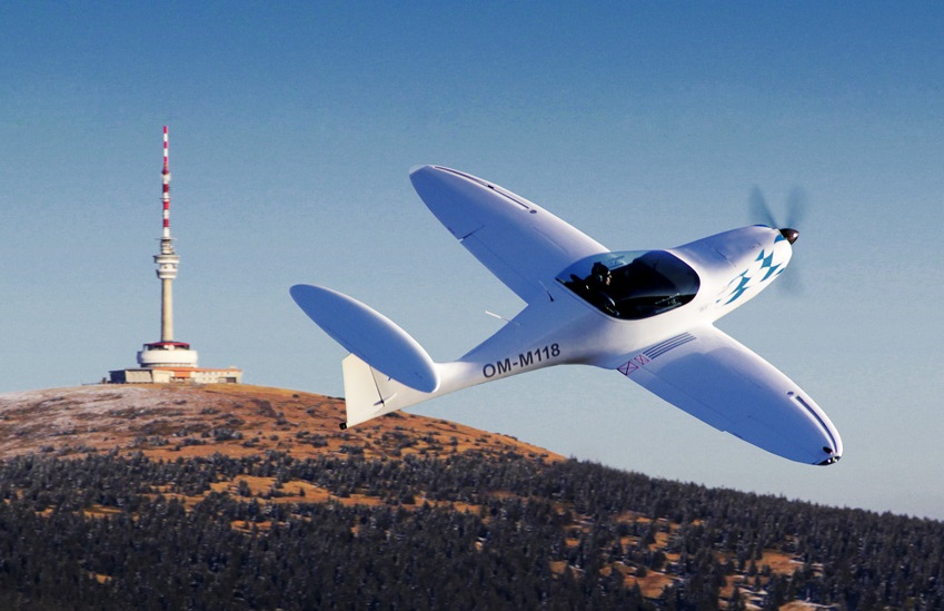
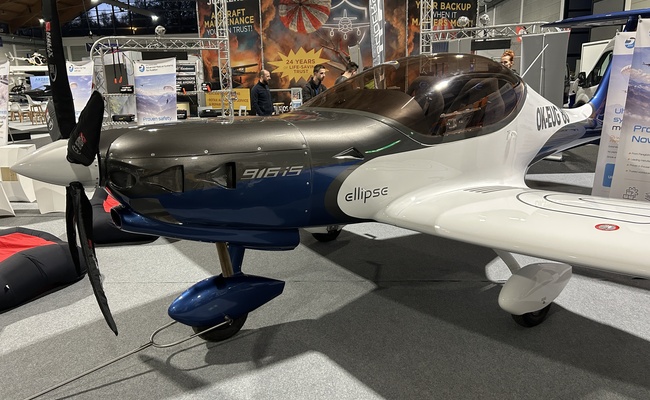
So far, it seems that an elliptical wing is not as advantageous in practice as it may seem at first sight. However, the negative consequences of the choice of an elliptical planform can be solved by a suitable combination of various design elements and, as can be seen in real aircraft with an elliptical wing, quite successfully. The following section will discuss how the elliptical wing was solved on the Ellipse Spirit ultralight aircraft.
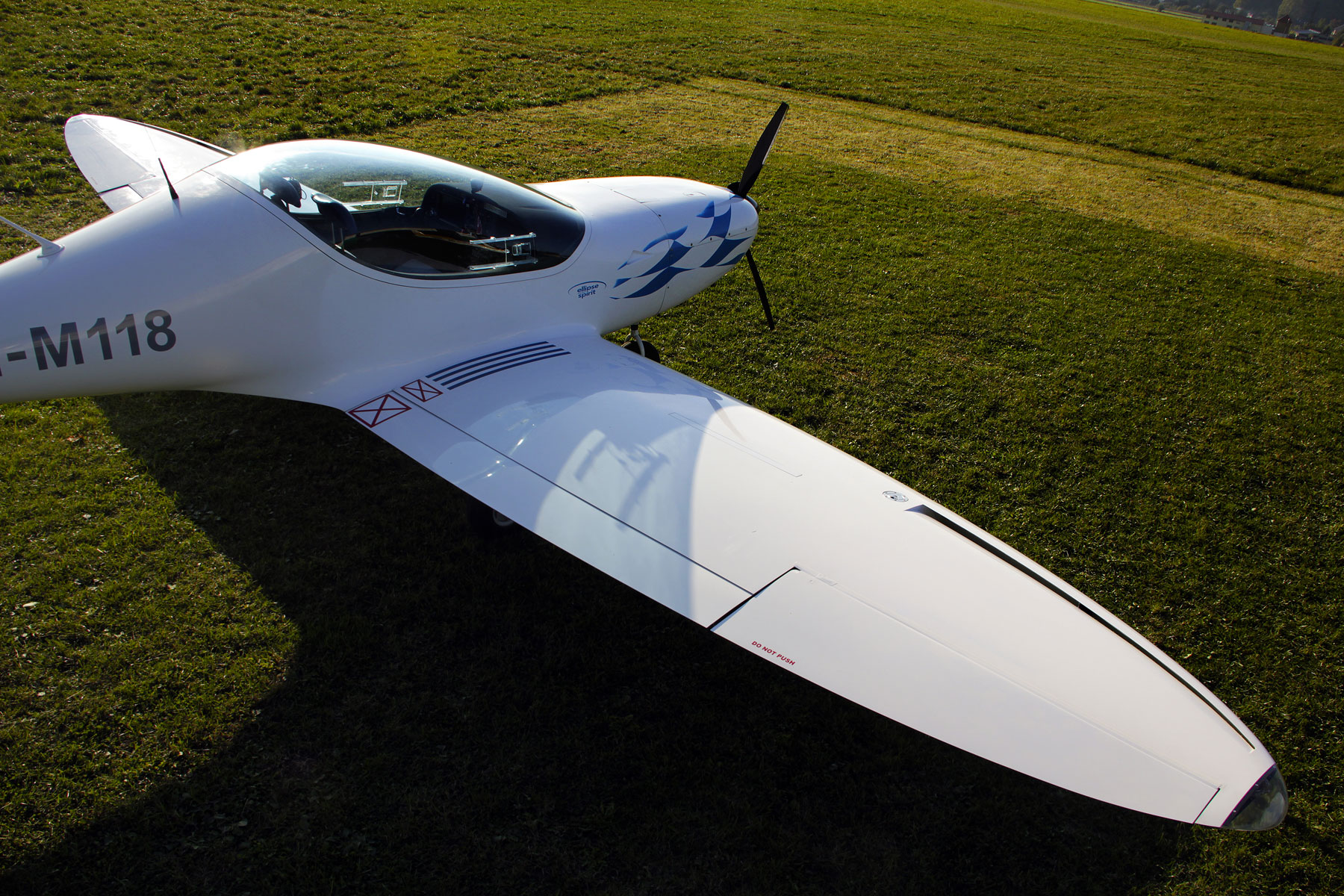
Ellipse Spirit ultralight wing
The demands on the wing of the Ellipse Spirit were not low. It was necessary to meet the building code in terms of minimum speed, while requiring a high cruising speed. It was also necessary to ensure favourable stall characteristics of the wing, as a safe aircraft is a top priority for the manufacturer. And all this had to be realised on an elliptical wing.
Finding a compromise between these totally conflicting requirements is very difficult. Therefore, no compromise was made and this led to the result, which is a unique concept that approaches the design of an elliptical wing in a completely different way.
The first requirement was high travel speed. This means minimising drag. And once the elliptical wing was chosen, it was decided that it was a shame to spoil this optimal solution by twisting. It was therefore left untwisted, thus minimizing the induced drag. However, the most significant component of drag at high speeds is the frictional drag of the wing, which meant that the wing area had to be reduced.
The small wing area affected (but also facilitated) the solution to the second requirement - minimum speed. Assuming we have a low wing area, the required minimum speed can be achieved just by increasing the lift coefficient. Therefore, a very efficient Fowler flap with a lift coefficient of 3.2 was chosen.
As can be guessed, such a sharply uncompromising wing concept must cause problems somewhere. This was indeed the case. Not so much in the flight configuration, where the aircraft's behaviour might not have been so tragic, but in the landing configuration.
The combination of a strong lift flap and an untwisted elliptical wing must cause flow separation on the aileron. And the difference between the profile maximum lift coefficient and the lift coefficient from stagger is really high. This is where it stops being simple and straightforward, because there are several conflicting influences. The situation is somewhat improved by the fact that the critical angle of attack of the airfoil with the flap is much lower than the critical angle of attack of the airfoil itself, which could result in the separation occurring earlier on the flap than on the aileron.
An extended flap, on the other hand, causes an increase in the induced angle of attack on the ailerons. It is also important to note that the lift line is not a straight line up to break-off (Glauert's method is semi-linear) and the peak of the lift line may be significantly different for the airfoil alone and the airfoil with flap. Finally, the flow around the wing is three-dimensional, and among other phenomena there are various end vortices that can, for example, locally prevent detachment, etc.
It was therefore necessary to find a way to provide sufficient lift coefficient margin on the aileron without significantly degrading the wing itself, in order to retain the benefits of an elliptical wing. This solution was a slot in the leading edge of the wing, located in the aileron area.
The slot, as a classical means of increasing lift, is able to tolerate significantly higher critical angles of attack of the airfoil and, secondly, to provide higher values of the lift coefficient (unlike the flap, where the lift coefficient is increased but the critical angle of attack is also decreased).
This eliminates the risk of flow separation in the aileron region, which is due to the increase in induced angle of attack caused by the deployed flap. The critical angle of attack of the slotted airfoil is higher than the induced angle of attack in the aileron region.
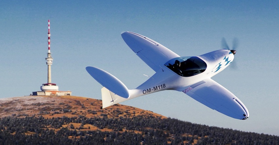
As a result, the installation of the slot in front of the aileron has given the aircraft additional excellent characteristics that were not originally considered at all. First of all, the wing has gained an excellent passive safety feature, because the slot, which was designed for the landing mode, naturally protects the aileron from tearing off even in a very high margin flight configuration.
This means that the ailerons are functional even when the flow is torn off on the remaining wing area, and they even work directly during a stall. This also makes the aircraft capable of controlled flight at high angles of attack. Furthermore, the aircraft is closer to the STOL category, i.e. aircraft with short take-off and landing lengths.
The final question is whether the slot has too high a drag coefficient that would negate any advantages gained. Of course, an increase in drag coefficient is inevitable, but its overall effect on wing drag is not very significant. It is important to note that all drag coefficients are converted to total wing area and therefore the area of the wing area with the slot, which is only a fraction of the total wing area, contributes only a proportionate part to the total drag of the airplane.
Furthermore, the absolute value of the drag coefficient of the slotted airfoil in cruise mode is only slightly higher than that of the clean airfoil. As a result, the decrease in the maximum speed of the aeroplane in the horizon due to the slot is only in the order of units of km/h, which has been verified by flight tests.
In conclusion, this unique approach has succeeded in designing an elliptical wing with exceptional characteristics that have already been confirmed by flight tests. So there is nothing to do but to look forward to seeing the aircraft live and experience its unique characteristics in flight.
Ing. Martin Vyskočil
Resources used
Software Glauert III: VANĚK, F.; HLINKA, J. Glauert III. 2003, Institute of Aerospace Engineering Brno.
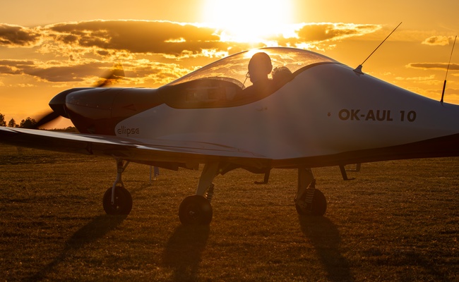
Photographs and video recordings from the property of A2CZ, manufacturer of the Ellipse Spirit ultralight aircraft.
Comments on the pictures
Fig. Example
Output from Glauert III. Individual components contributing to the resulting lift coefficient distribution along the wingspan. An example is a twisted trapezoidal wing. The faint dark green line represents the local maximum profile lift coefficient. The black colour is the lift coefficient distribution of an untwisted trapezoidal wing.
The contribution from the geometric twist of the wing is shown in green and the contribution from the deployed flap in blue. The superposition of these components is expressed by the red line, and at the same time this distribution is plotted at maximum lift coefficient, and the small green point expresses the point from which the flow separation starts to propagate on the wing.
Fig. Extended flap
An elliptical wing with the flap extended. The Ellipse Spirit wing in UL version is modeled. The figure describes a situation where there is no slot on the wing. The area of the wing where the red curve of the resulting lift coefficient distribution is higher than the local maximum airfoil lift coefficient is the blast where the flow separation should occur. The area to the left of the deployed flap belongs to the fuselage.
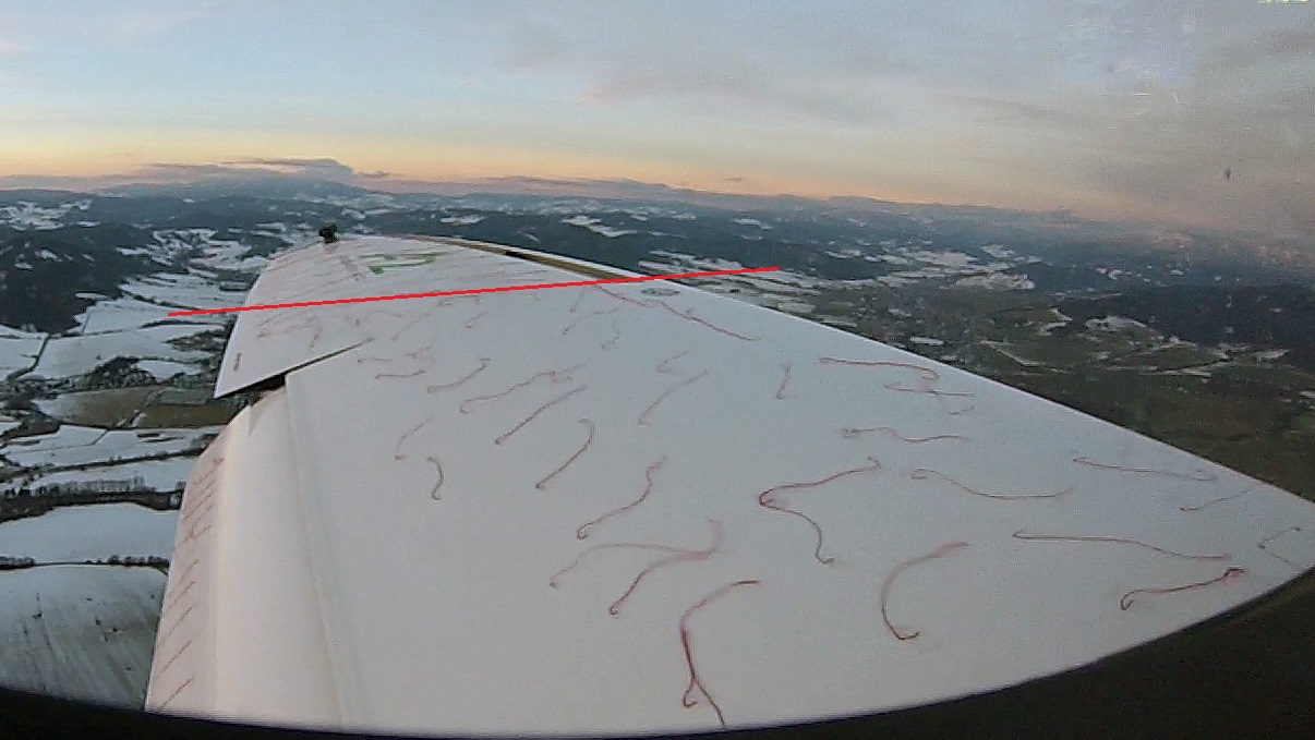
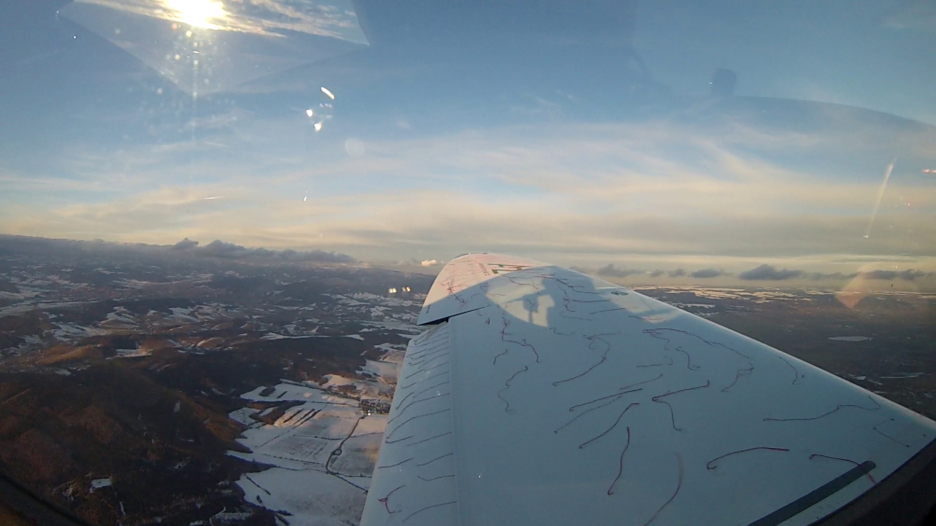
Figures 3 and 4
Images from video footage of Ellipse Spirit flight tests. Both images were taken in a situation where the flow was detached on the entire wing. Fig. 3 is a normal production wing of the aircraft with a slit. The red line marks the boundary where the jet detachment propagation stopped.
The portion of the wing from this line to the end (i.e., a substantial portion of the ailerons) is quite visibly protected from detachment, and the cottons reveal normal wing wrapping even during stall. Fig. 4 is the same wing with the slit covered. Detachment on the entire wing is quite evident and this difference shows the importance of this slit in the aerodynamics of the wing.